
")
General Information:
Cooling towers are a critical component of production in multiple industries today. They are used in power plants, chemical plants, refineries, food processing units and large buildings (HVAC). Cooling towers mostly act as heat exchangers to cool water from hot temperature to required normal temperature and in direct cooling equipment to remove heat from water discharge. There are two types of cooling tower fans. The first type of cooling tower fan is called a gearbox driven fan. This type of fan has the motor mounted to the side of the fan’s cell and drives the fan using a shaft. The other type of cooling tower fan is called a belt driven fan. This type of cooling tower fan has mounted inside the fan’s cell meaning that both components are in the air flow. Catastrophic failure of a cooling tower can result in the failure of other equipment, safety hazards, lowered production and expensive repairs. So it is important that they be monitored regularly.
Cooling towers are a critical component of production in multiple industries today. They are used in power plants, chemical plants, refineries, food processing units and large buildings (HVAC). Cooling towers mostly act as heat exchangers to cool water from hot temperature to required normal temperature and in direct cooling equipment to remove heat from water discharge. There are two types of cooling tower fans. The first type of cooling tower fan is called a gearbox driven fan. This type of fan has the motor mounted to the side of the fan’s cell and drives the fan using a shaft. The other type of cooling tower fan is called a belt driven fan. This type of cooling tower fan has mounted inside the fan’s cell meaning that both components are in the air flow. Catastrophic failure of a cooling tower can result in the failure of other equipment, safety hazards, lowered production and expensive repairs. So it is important that they be monitored regularly.
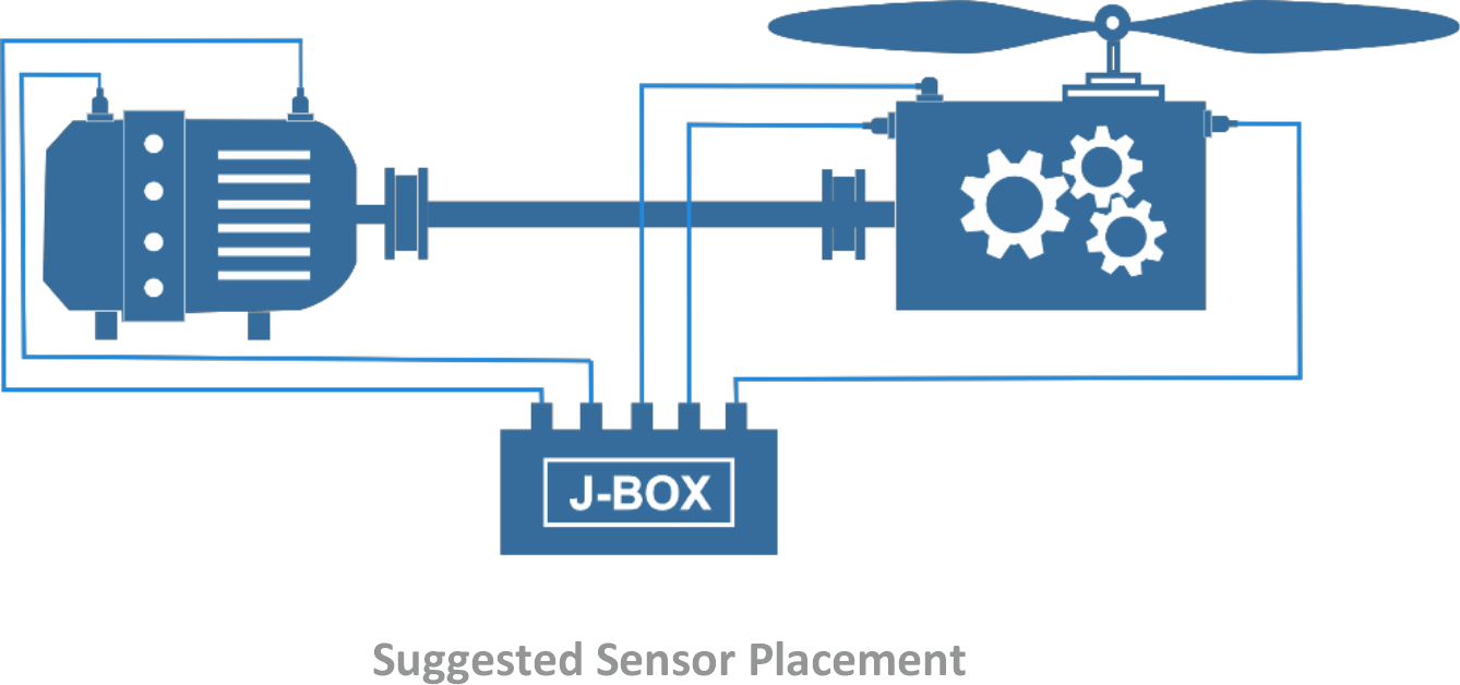
Cooling Towers are made up of a Motor, Gearbox, Fan and connecting Jackshaft. The Gearbox translates the motors 1500/1800 RPM to a lower RPM for the Fan. Fan Speed varies from less than 100 RPM to a few hundred RPM depending on diameter. Rolling Element Bearings are standard and should be monitored using properly placed Industrial Accelerometers. Care must be taken to waterproof all Accelerometer connectors by flooding with Silicone Grease. For Monitoring Systems the LF (Low Frequency) option should be selected for the low speed gearbox shaft.
Only “X” or Horizontal Accelerometers marked in Red are recommended for Full Time Vibration Monitoring (Protection) System. Walk Around Data Collector or PdM Programs usually require “X” Horizontal (Red), “Y” Vertical (Green) and “Z” Axial (Yellow) Sensors for analysis. When economic decisions must be made to reduce sensor count due to the size or criticality of the Motor Driven Pump “X” or horizontal sensors should be installed first as they are closer to the load zone of the bearing and in direction of freedom of movement.
Cooling Tower Vibration Measurement:
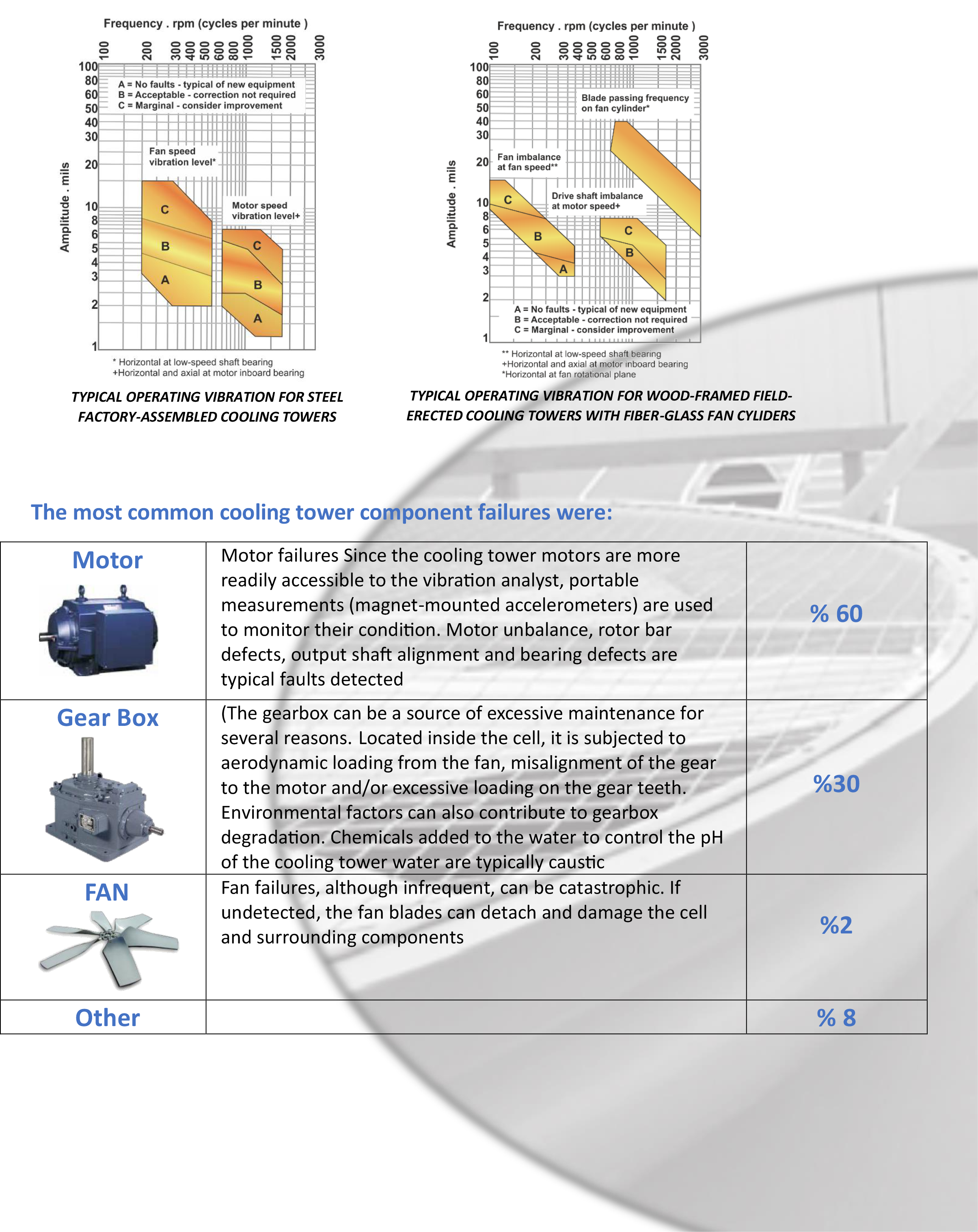
Cooling tower fans operate under different load conditions. They often only run at peak load for short periods. With differing stresses over a prolonged period, the mechanical components can develop degraded performance, which leads to failure. As with any rotating equipment, bearing and gear failures, misaligned drive shafts, and excessive vibration are common. On the other hand, the structure of a cooling tower makes collecting vibration data on the gearbox difficult and dangerous without permanently installed sensors i.e. while the motor is often accessible, the gearbox and fans are usually located inside the cooling tower cell, making these components inaccessible while the fan is in operation. Because the gearbox is a typical failure point, lack of feedback on the machine’s health puts you at risk for unexpected failure. Data collected during a case study at a Bristol- Myers Squibb plant found that the most common failures in cooling tower components were related to the motor (60 percent of the time), the gearbox (30 percent of the time), the fan (two percent of the time), with other tower components making up for the rest of the failures. The classic legacy solution involved the use of earthquake mechanical switches. These devices utilized spring and magnet concept-based mechanical switches to shut down the fan in case of high vibration amplitudes. Reliability becomes an issue with mechanical switches due to harsh cooling tower environments, especially in critical applications. In fact like every other application cooling towers have their own application issues which may be summarized as:
Cooling tower fans operate under different load conditions. They often only run at peak load for short periods. With differing stresses over a prolonged period, the mechanical components can develop degraded performance, which leads to failure. As with any rotating equipment, bearing and gear failures, misaligned drive shafts, and excessive vibration are common. On the other hand, the structure of a cooling tower makes collecting vibration data on the gearbox difficult and dangerous without permanently installed sensors i.e. while the motor is often accessible, the gearbox and fans are usually located inside the cooling tower cell, making these components inaccessible while the fan is in operation. Because the gearbox is a typical failure point, lack of feedback on the machine’s health puts you at risk for unexpected failure. Data collected during a case study at a Bristol- Myers Squibb plant found that the most common failures in cooling tower components were related to the motor (60 percent of the time), the gearbox (30 percent of the time), the fan (two percent of the time), with other tower components making up for the rest of the failures. The classic legacy solution involved the use of earthquake mechanical switches. These devices utilized spring and magnet concept-based mechanical switches to shut down the fan in case of high vibration amplitudes. Reliability becomes an issue with mechanical switches due to harsh cooling tower environments, especially in critical applications. In fact like every other application cooling towers have their own application issues which may be summarized as:
⇒ Effect of flexibility of the tower on vibration amplitudes
⇒ High vibration values during startup
⇒ Usage of complex speed-reducing gearboxes (1500/120 RPM)
⇒ Effect of neighboring cells on the measurement i.e. starting cell 2 may shut down cell 1
⇒ Speeds are slow based on the linear velocity of the tip of the blade leading to the necessity of a vibration analyzer capable of processing low speeds and frequencies.
⇒ Water build up in blades and corrosion from bad pH and acidic environments
⇒ Reversing fans in cold climates
⇒ The often have large distances to control room
⇒ Lack of ease of access to gearboxes and fan bearings for vibration analysis with portable data collectors
Cooling Tower Vibration Diagnostic:
Vibration monitoring offers a vital early warning, enabling engineers to take action before any substantial damage is caused. Access to continuous data and on-line vibration measurement allows you to detect problems before they lead to failure, providing insight into the health of cooling tower gearboxes and motors. Vibration alerts warn of pending problems, enabling further investigation to detect and diagnose the fault so maintenance can be scheduled. Vibration and temperature measurement would lead to the identification of a number of mechanical faults with predictive diagnostics such as:
Vibration monitoring offers a vital early warning, enabling engineers to take action before any substantial damage is caused. Access to continuous data and on-line vibration measurement allows you to detect problems before they lead to failure, providing insight into the health of cooling tower gearboxes and motors. Vibration alerts warn of pending problems, enabling further investigation to detect and diagnose the fault so maintenance can be scheduled. Vibration and temperature measurement would lead to the identification of a number of mechanical faults with predictive diagnostics such as:
⇒ Imbalance
⇒ Water intrusion
⇒ Misaligned drive shaft
⇒ Rolling element bearing failure
⇒ Chipped, broken, or worn gear teeth
⇒ Resonance
⇒ Water intrusion
⇒ Misaligned drive shaft
⇒ Rolling element bearing failure
⇒ Chipped, broken, or worn gear teeth
⇒ Resonance
⇒ Misaligned gears
⇒ Bent shaft
⇒ Damaged couplings
⇒ Lubrication problems
⇒ Structural and mechanical looseness
⇒ Bent shaft
⇒ Damaged couplings
⇒ Lubrication problems
⇒ Structural and mechanical looseness
Standard and Alert and Trip Chart:
Several international standards like ISO 14694 or CTI (Cooling Technology Institute) Ch#10 have been developed for cooling tower vibration measurement and analysis. Allowable vibration levels for cooling towers in picture below is adapted from Chapter 10 Cooling Tower Manual, published by the Cooling Tower Institute, Houston, TX, Feb 90.
Several international standards like ISO 14694 or CTI (Cooling Technology Institute) Ch#10 have been developed for cooling tower vibration measurement and analysis. Allowable vibration levels for cooling towers in picture below is adapted from Chapter 10 Cooling Tower Manual, published by the Cooling Tower Institute, Houston, TX, Feb 90.
Mounting:
The most common positions to monitor are :
Motor: Drive End (DE) and non-drive end (NDE) where you will be mounting the sensor radially to monitor the motor bearing condition (g).
Gearbox: input and output shafts; the sensor will be mounted radially. This enables the condition of the bearings (g) and fan out of balance (velocity) to be monitored. An optional axial accelerometer on the input shaft would give a good indication of the thrust on the shaft.

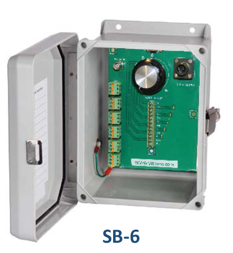
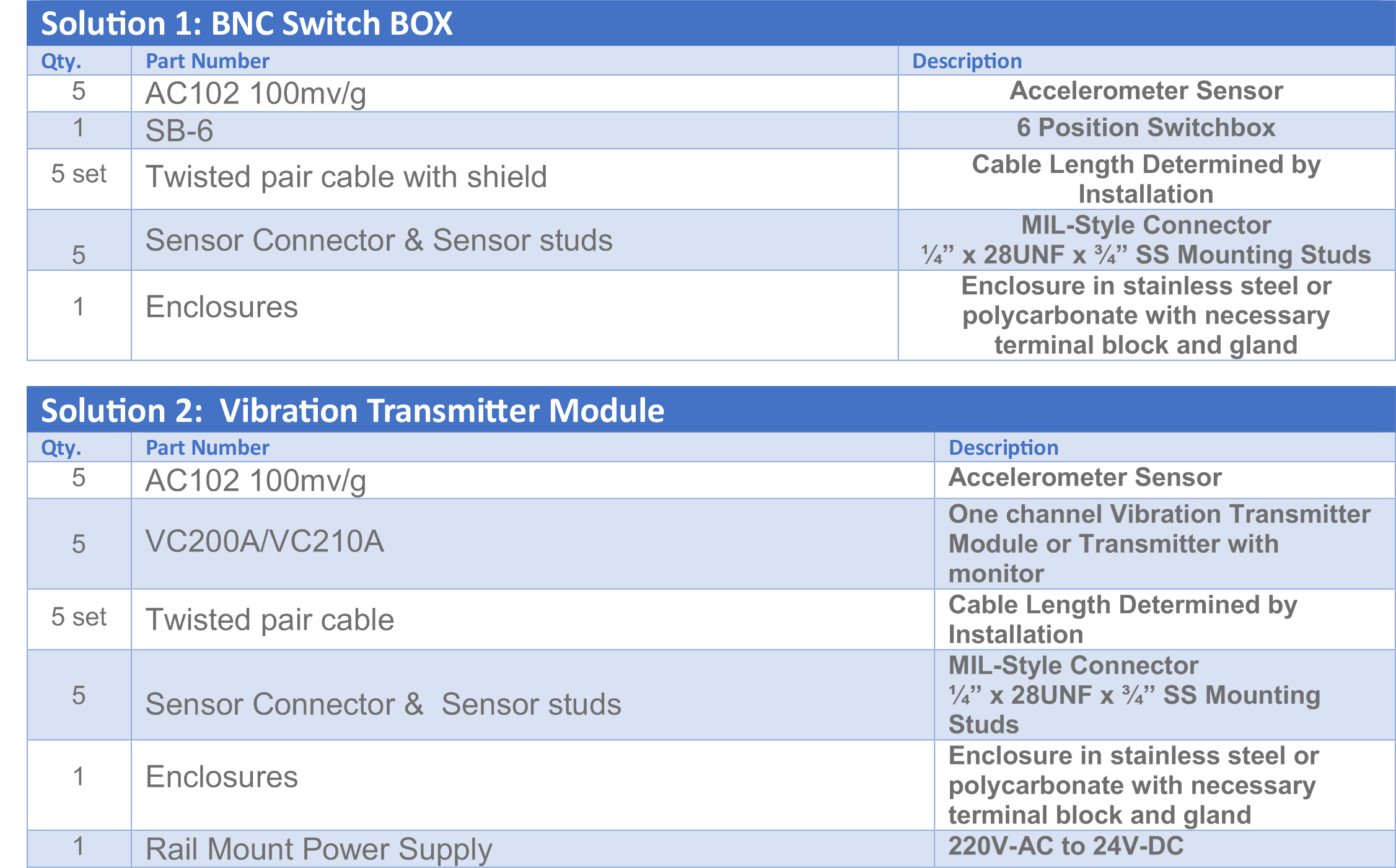
BNC Switch BOX Model SB-6:
Recommended for walk around data collection routines, where the transducer is fixed and installed. Because changing the direction and point of measurement might affect measurement values, permanently mounted Accelerometers provide more reliable and repeatable readings and the local BNC Switch Box allows for faster, safer and more convenient data collection with portable data collectors or vibration analyzers. VIBSENS switch box works with all 3rd party data collectors and vibration analyzers.
Recommended for walk around data collection routines, where the transducer is fixed and installed. Because changing the direction and point of measurement might affect measurement values, permanently mounted Accelerometers provide more reliable and repeatable readings and the local BNC Switch Box allows for faster, safer and more convenient data collection with portable data collectors or vibration analyzers. VIBSENS switch box works with all 3rd party data collectors and vibration analyzers.

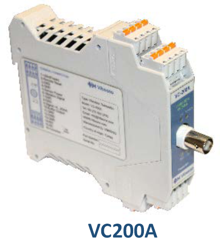
Vibration Transmitter Module Model VC200A:
This stand-alone analogue module which applies dynamic signal protection meets the requirements of API-670 and provides all the features of a standard vibration protection system able to excite relay output & transmit 4-20mA signal proportional to acceleration, velocity, or displacement to PLC/DCS or any standard 3rd party recorder. Moreover, BNC output for reading with portable data collectors, optional internal integrator, and transducer check display LED, current loop check, alarm relay outputs are all provided in just one module. Optional selection between delays in alarm, energized and non-energized relays are also embedded. Terminal for remote reset for alarm ignorance is also provided. It may be connected either to an ICP™ accelerometer or a proximity displacement probe, VC200A is a complete system which simply needs DC power supply and connected transducer with easy setup.
This stand-alone analogue module which applies dynamic signal protection meets the requirements of API-670 and provides all the features of a standard vibration protection system able to excite relay output & transmit 4-20mA signal proportional to acceleration, velocity, or displacement to PLC/DCS or any standard 3rd party recorder. Moreover, BNC output for reading with portable data collectors, optional internal integrator, and transducer check display LED, current loop check, alarm relay outputs are all provided in just one module. Optional selection between delays in alarm, energized and non-energized relays are also embedded. Terminal for remote reset for alarm ignorance is also provided. It may be connected either to an ICP™ accelerometer or a proximity displacement probe, VC200A is a complete system which simply needs DC power supply and connected transducer with easy setup.
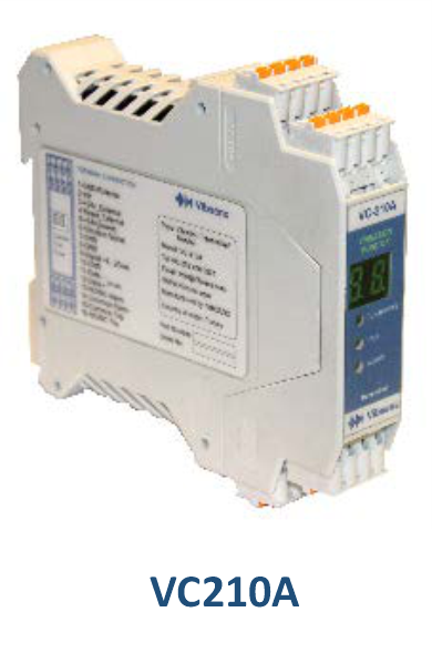
Vibration Monitor/ Transmitter Module Model VC210A:
VC210A not only has the features of the above mentioned product VC200A but also provides two separate relay outputs as Alarm and Trip, and has a display which shows the overall vibration values and can transmit 4-20mA signal proportional to acceleration, velocity, or displacement to PLC/DCS or other recorders. Optional signal integration and status LED (OK/Alert /Danger) is provided for each module. Moreover, the ability to select alarm delay, bypass, latching or non-latching relays, energise and non-energised relays, Terminal for remote reset, Modbus RTU (RS-485) protocol communication are also supported in this device.
Enclosure:
VIBRASENS is able to provide a wide variety of custom enclosures that are supplied fully wired and only require transducer input wires, 4-20mA output signal, relay outputs and power supply to be connected to terminal blocks. Complete system installation is provided with 30cm x 25cm x 15cm housing for switch box and transmitters with optional fiberglass / stainless steel enclosure with a stainless steel back plane, which the customer can easily choose and order with vibration transmitter or monitor modules.

VibSens is ready to propose to you the most cost effective and efficient solution for vibration monitoring & protection even in renewal or upgrade projects.
-Vibsens systems are all capable to measure and acquire signals from transducers provided by other 3rd party hardware and are fully compliant with other monitoring systems.
-There is device configuration software for all devices which support Modbus RTU (Vibsens-CNFG)
-Vibsens presents full engineering services & solutions for factories from project management, system design to installation, commissioning, training, calibration and customer support in the field of vibration measurement & protection.
-Hazardous areas: Please contact us for explosion-proof versions or consultancy on installation.
-All of our products do come with a general warranty which ensures Vibsens products to be free from any defects or malfunctions in material and operation , As long as the product is used incorrectly, the natural disaster, improper installation or repair that caused the defect