")
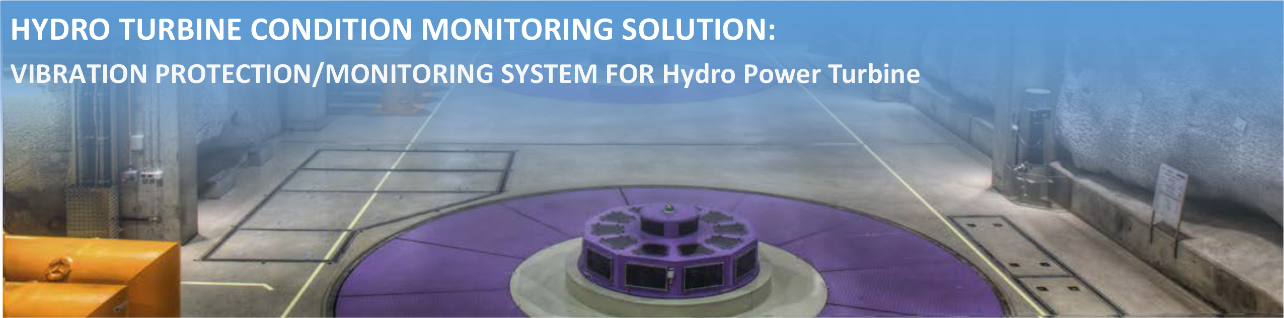
Hydro power generation :
Without reliable health monitoring systems to actively monitor and protect hydro machinery’s health, hydro power generation in extreme load zones may encounter severe problems. Moreover, hydroelectric turbines operate at low speeds, with faults appearing as low as 0.5 Hz; therefore analyzing the health of the unit requires special monitoring hardware capable of detecting these extremely low frequencies.
As hydro turbine health degrades, performance decreases, generation declines, and unplanned shutdowns are possible. Operating this machinery requires special load considerations and monitoring equipment designed for its unique needs.
Hydro turbine condition monitoring :
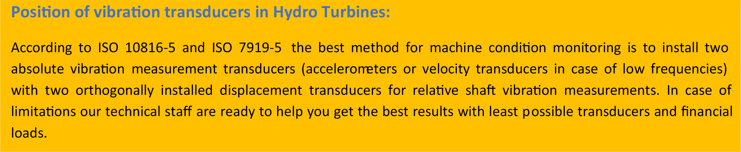
Use of vibration and process control parameter monitoring and machinery protection systems on large rotating machines has long been recognized as a valuable tool in the prevention of component and machinery failure. Several international standards have been developed exclusively for hydro machinery. Some of these standards have been summarized here for introduction:
EN 60994, GB/T 11348.5, GB/T 17189,
ISO 10816-6, ISO 7919-5 and ISO 10817.
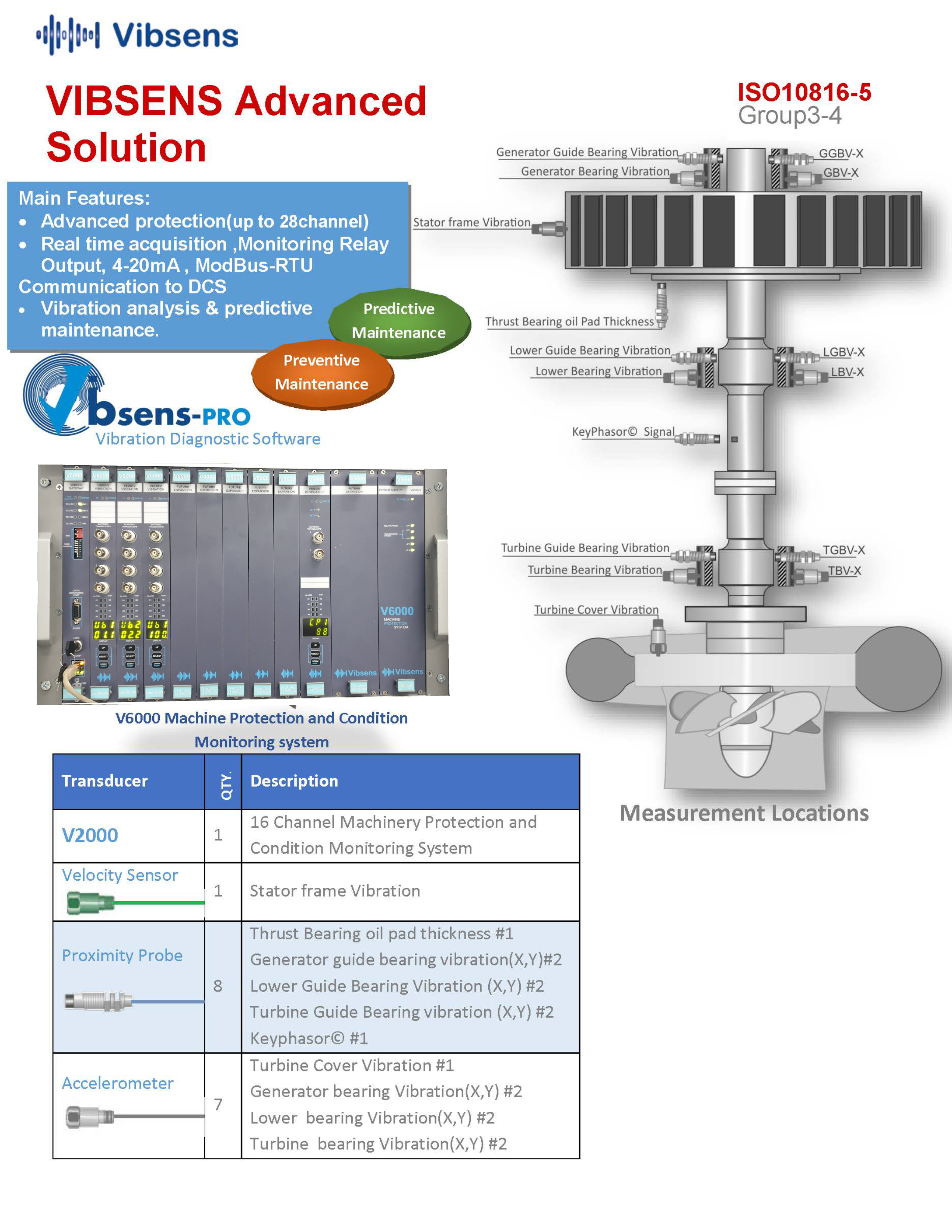
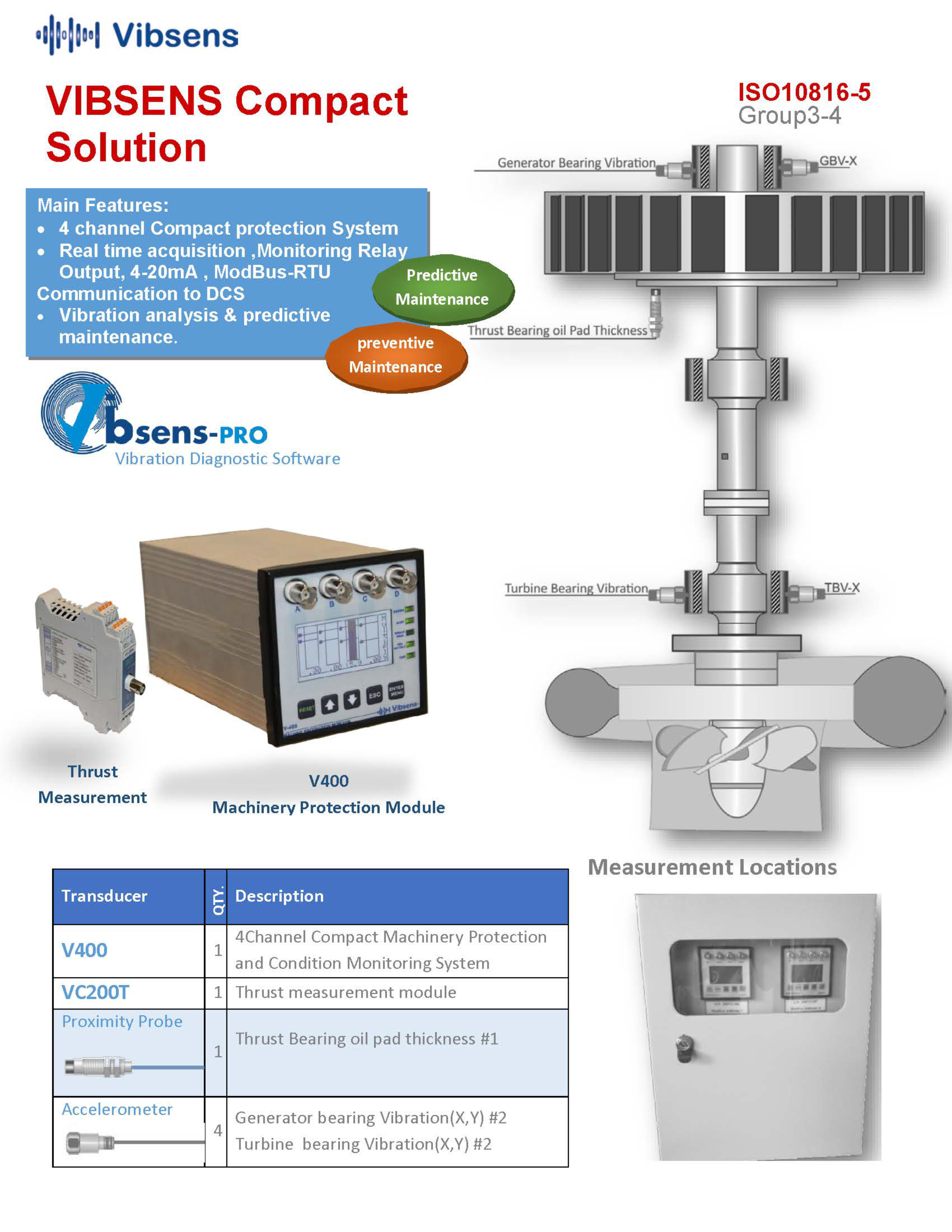
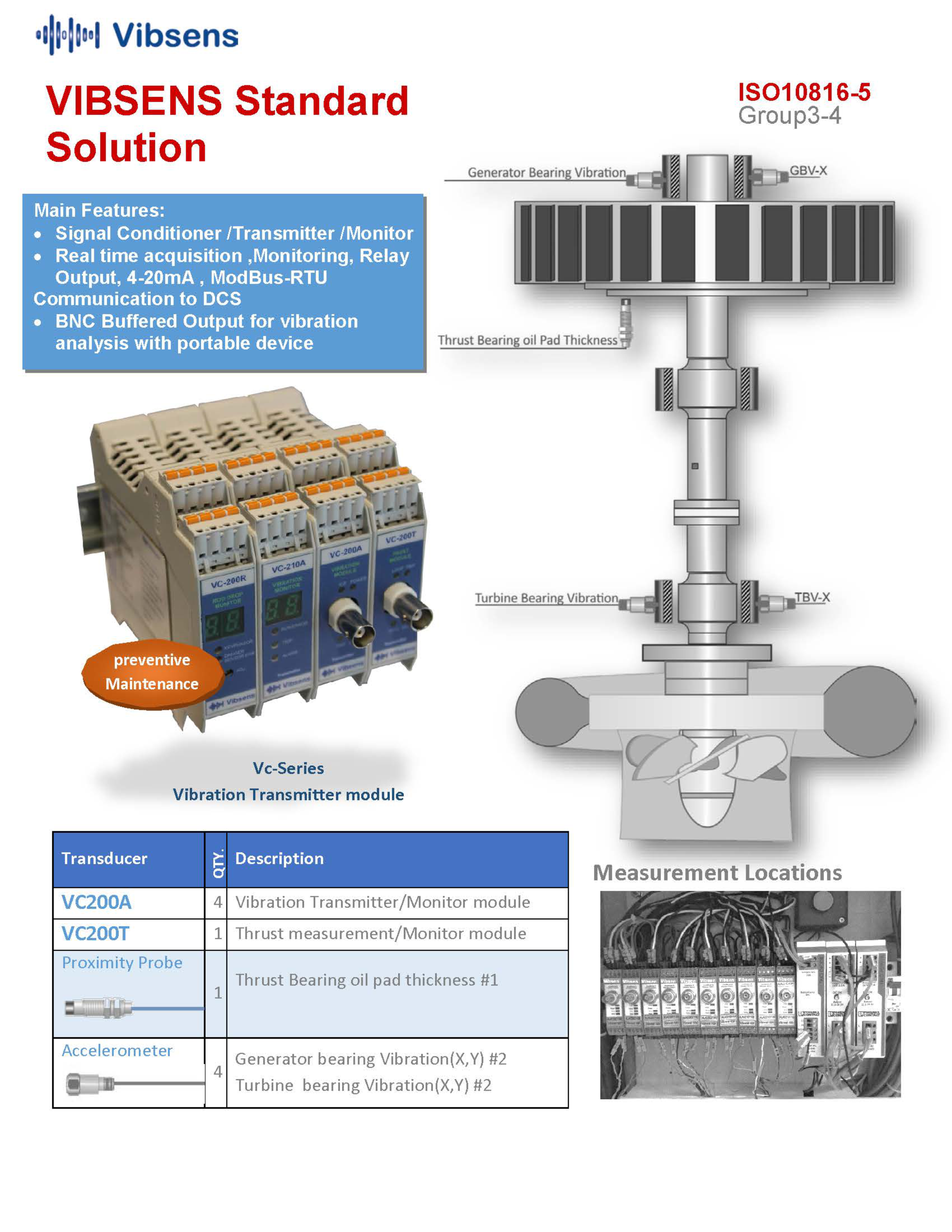
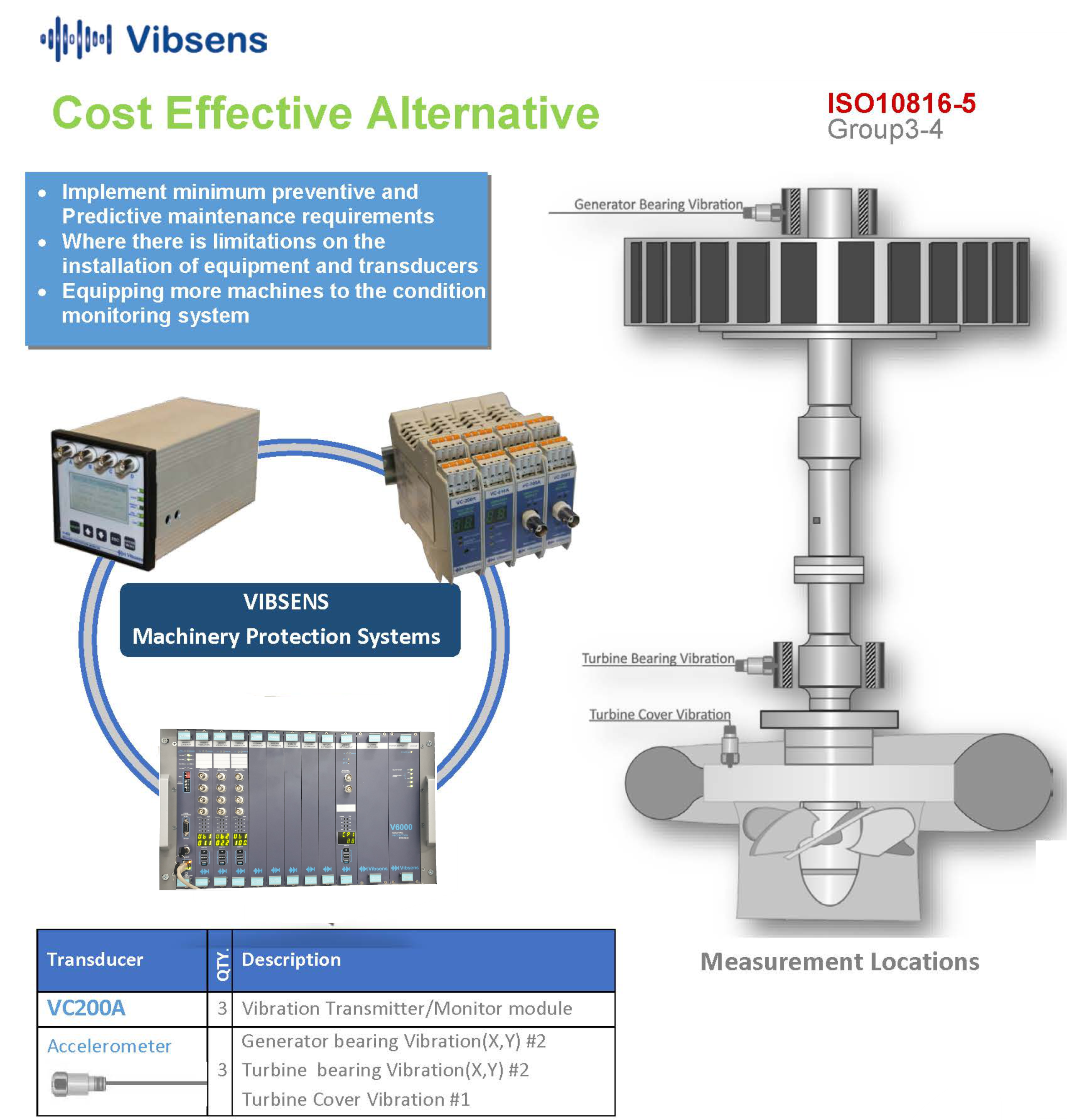
In accordance with the mentioned standards, VibSens has developed a specific condition monitoring & protection system customized for hydro turbines and generators. In addition to the mentioned above requirements, a complete set of useful monitoring parameters and display functions have been added to increase The efficiency of the maintenance policies to ensure the continued good health of the power generating assets and to detect underlying problems early.VibSens hydro turbine condition monitoring system integrates machinery health data to process control parameters, allowing the user to correct issues before they affect power generation.
Use of vibration and process control parameter monitoring and machinery protection systems on large rotating machines has long been recognized as a valuable tool in the prevention of component and machinery failure. Several international standards have been developed exclusively for hydro machinery. Some of these standards have been summarized here for introduction:
EN 60994, GB/T 11348.5, GB/T 17189,
ISO 10816-6, ISO 7919-5 and ISO 10817.
In accordance with the mentioned standards, VibSens has developed a specific condition monitoring & protection system customized for hydro turbines and generators. In addition to the mentioned above requirements, a complete set of useful monitoring parameters and display functions have been added to increase The efficiency of the maintenance policies to ensure the continued good health of the power generating assets and to detect underlying problems early.VibSens hydro turbine condition monitoring system integrates machinery health data to process control parameters, allowing the user to correct issues before they affect power generation.
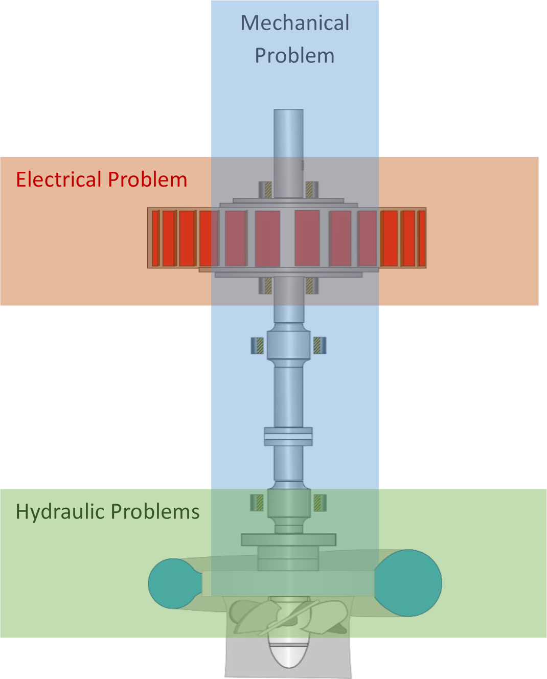
Main Problems:
There are three main types of hydro turbine generating unit problems which are common among most of them and categorized as most probable malfunctions:
-Electrical problems
-Mechanical problems
-Hydraulic problems.
To measure each of these categories, procedures have been developed to associate each of these problems with at least one measurement.
Transducer selection:
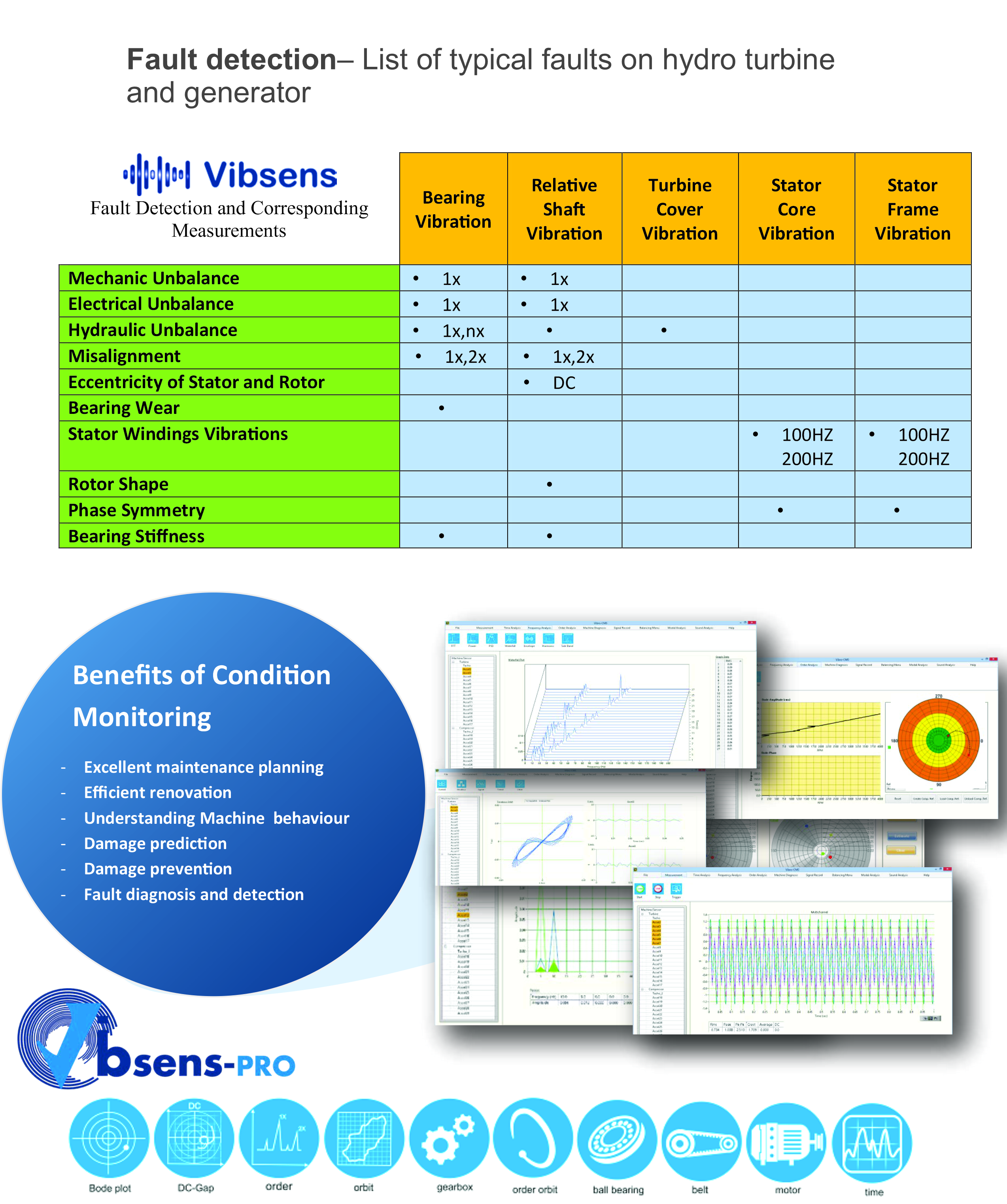
1) Electrical problems which mostly occur are stator bar/winding vibration, insulation breakdown, and rotor pole problems. These problems are measured by:
-Stator frame / Velocity or End winding accelerometer
2) Mechanical problems which occur mostly in hydro generating units are unbalance, shaft misalignment, bearing vibration, bearing and seal excessive clearance fluctuations and stator & rotor deformation. These malfunctions are measured by:
-2 perpendicularly installed proximity probes to measure radial vibrations
-Bearing RTD/thermocouple to monitor bearing temperature
-Bearing housing velocity/ acceleration
-Thrust measurement to monitor oil film
-Stator vibration and movement
3) Hydraulic problems which mostly occur are flow instabilities like cavitation and rough load zone(Vortex) and are measured by:
-Axial and X-Y radial proximity probes
-Axial and radial Accelerometer transducers
Mechanical Arrangement:
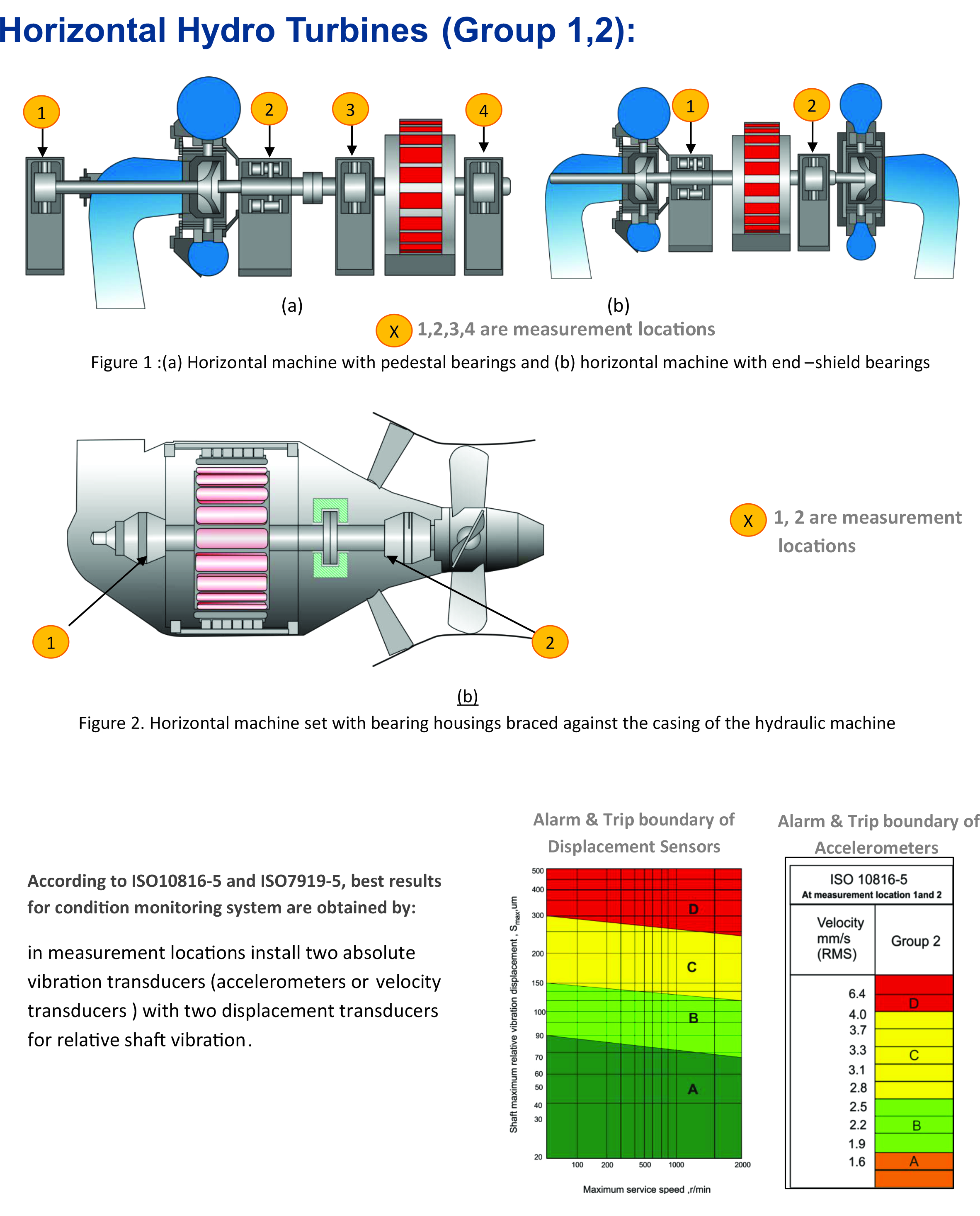
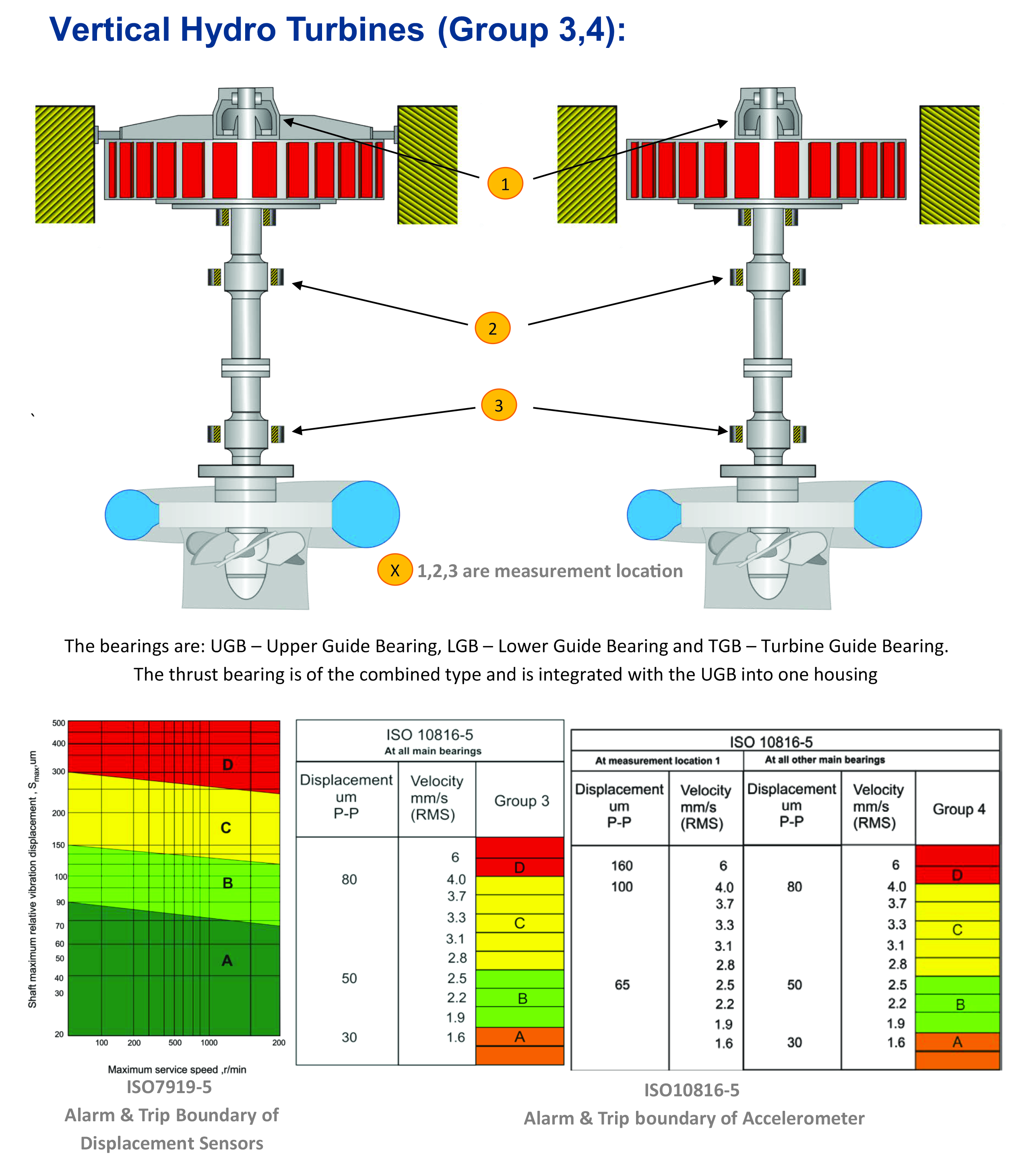
Due to significant differences in design and arrangement, hydraulic machines areseparated into four principal groups as per radial bearing stiffness and are as follows
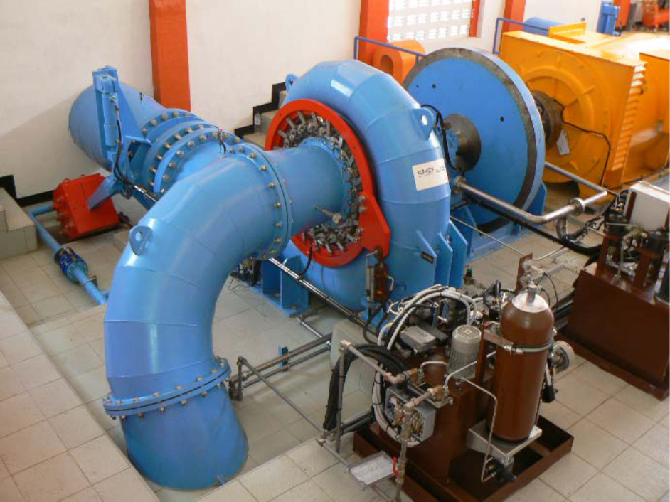
Group 1: Horizontal machine sets with pedestal or end-shield bearings mounted on a rigid foundation, usually with operational speeds of above 300 rpm. (fig. 1 a,b)
Group 2: Horizontal machine sets with bearing housings which are only braced against the casing of the hydraulic machine, usually with operational speeds of less than 300 rpm. (fig. 2)
Group 3: Vertical machine sets with bearing housings which are all braced against the foundation, usually with operational speeds of between 60 to 1800 rpm. (Fig. 3)
Group 4: Vertical machine sets with lower bearing housings braced against the foundation and upper bearing housings braced against the generator stator only, usually with operational speeds of between 60 to1000 rpm. (Fig. 4)
Due to significant differences in design and arrangement, hydraulic machines areseparated into four principal groups as per radial bearing stiffness and are as follows
Group 1: Horizontal machine sets with pedestal or end-shield bearings mounted on a rigid foundation, usually with operational speeds of above 300 rpm. (fig. 1 a,b)
Group 2: Horizontal machine sets with bearing housings which are only braced against the casing of the hydraulic machine, usually with operational speeds of less than 300 rpm. (fig. 2)
Group 3: Vertical machine sets with bearing housings which are all braced against the foundation, usually with operational speeds of between 60 to 1800 rpm. (Fig. 3)
Group 4: Vertical machine sets with lower bearing housings braced against the foundation and upper bearing housings braced against the generator stator only, usually with operational speeds of between 60 to1000 rpm. (Fig. 4)
Measurement Type:
-For low-speed machines (below 300 rpm), the preferred measurement quantity is the vibration displacement Sp-p (peak to peak displacement)If the spectrum is expected to contain high-frequency components, the evaluation should normally be based on broad-band measurements of both displacement and velocity
-For medium- and high-speed machines (300 to 1800 rpm), the preferred measurement quantity is the vibration velocity vrms. If the spectrum is expected to contain low-frequency components, the evaluation should normally be based on broad-band measurements of both velocity and displacement
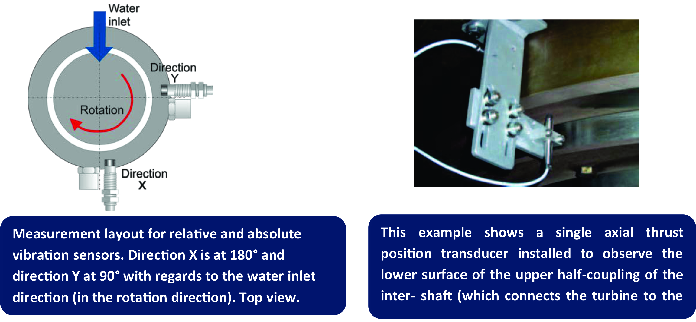
Measurement Directions:
The directions in which the displacement and acceleration sensors were placed are shown in picture below.
The directions in which the displacement and acceleration sensors were placed are shown in picture below.